Update: 04 January 2019
Past few days, I was struggling with my Articulated Jaw mechanism. After experiments, I discovered that even after several code tweaks in Manav AI’s Speech Synthesis algorithms, it fails to achieve real-time performance due to inherited delay within Serial UART communication between Raspberry Pi and Arduino, also known as Serial Latency, leading to extra overhead in program execution. Since I was struggling on Software side, I decided to start experiment at the hardware end. Therefore applying my past Knowledge on Digital Signal Processing and Electronics, I successfully developed the Amplitude Manipulated Articulate Jaw Mechanism(a.k.a AMAJM), an advanced articulated mechanism that can somewhat mimic the natural movement of Human mouth, with the help of movement triggered by the Amplitude of the input audio signal. I divided this post into multiple parts to briefly discuss the various stages of its development and challenges involved. So let’s get to it!
Arduino-Pi Serial Latency:
 A UART (Universal Asynchronous Receiver/Transmitter) is the device which ultimately controls the receive and transmit (read and write) operations performed by a given serial port. In particular, UARTs have dedicated memory in the form of a FIFO structure (first in first out - a queue structure) for each of the receive and transmit operations.
The purpose of the FIFO structures is to hold data either received from the serial port or to be written to the serial port. The Latency arises in the hardware during FIFO handling.
How do the FIFOs affect performance?
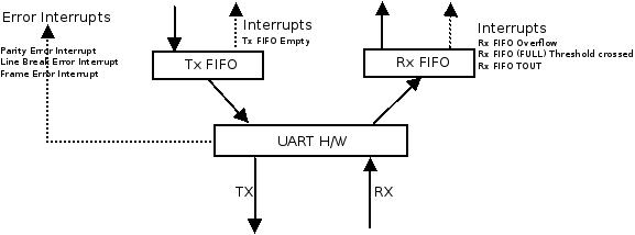 UART FIFO Interactions
The size of the FIFO buffers determines when the UART interrupts the CPU in order to transfer data between the FIFO and CPU memory (RAM, where applications running on the CPU have access to the data). Therefore, the size of the FIFOs can affect latencies in writing to and reading from the serial port (usually on the order of milliseconds), as well as overall performance of a given application.
For example, if you set the receive buffer to 1, the UART will interrupt the processor to transfer a single byte to CPU memory whenever a byte is received. While this will make a given byte available in RAM as soon as possible after arriving at the port, if data is continuously being received at the port, this will cause many interrupts. As a result, more CPU processing is dedicated to those interrupts which can decrease overall performance if other programs are running. Thus, if latencies on the order of a few milliseconds are tolerable for serial operations, it is often beneficial for overall performance to use a larger receive FIFO size.
In my case, the buffer size is 64 bytes(Arduino Uno) only. USB transfers are handled at a low level with high priority at Raspberry Pi. Also, there is some latency at Raspberry Pi end, plus I was sending approx. ~150+ bytes of data per second. There is no way that Python will be able to keep up with that. Hence this resulting in overall poor performance.
Amplitude Manipulated Articulate Jaw Mechanism(AMAJM):
“Any sufficiently advanced technology is indistinguishable from magic.” - Arthur C. Clarke
I designed AMAJM, a advanced articulated mechanism that can somewhat mimic the natural movement of Human mouth, with the help of movement triggered by the Amplitude of the input audio signal.
Roadmap:
Audio Input Sinusoidal wave on Oscilloscope in Real-Time
Amplitude is the maximum displacement or distance moved by a point on a vibrating body or wave measured from its equilibrium position. It is equal to one-half the length of the vibration path. In our case(Analog sound waves), it is the extent to which air particles are displaced, and this amplitude of sound or sound amplitude is experienced as the loudness of sound. The loudness perception of a sound is determined by the amplitude of the sound waves − the higher the amplitude, the louder the sound.
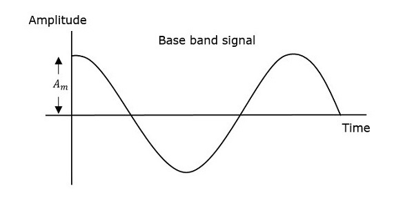 Amplitude(A)
The term “amplitude” is used to refer to the magnitude of oscillation, so the amplitude of the sinusoid “y = A × sin (ω×t)”, where A is the absolute value of Amplitude.
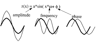 Sinusoid waveform
Therefore decided to use average (amplitude)loudness of the signal property as the base for my Humanoid’s articulated mechanism, which inspired from similar VU meter mechanism,
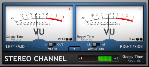 VU meter
A volume unit (VU) meter or standard volume indicator (SVI) is a device displaying a representation of the signal level in audio equipment. The VU-meter (intentionally) “slows” measurement, averaging out peaks and troughs of short duration, and reflects more the perceived loudness of the material than the more modern and initially more expensive PPM meters. For this reason, many audio practitioners prefer it to its alternatives, though the meter indication does not reflect some of the key features of the signal, most notably its peak level, which in many cases, must not pass a defined limit.
Circuit Designing(Simplified):
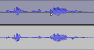
If you’ve ever recorded audio on your computer/phone, you may have seen it represented as a waveform as follows:
 Audio waveform(Audacity)
If you zoom in on this wave you will see that the shape is made of thousands of tiny oscillations back and forth.
This is called an audio signal and when we are dealing with audio signals in electronics, these oscillations represent oscillating voltages over time.
 oscillating voltages
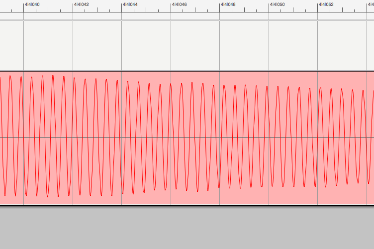
If we look at an audio signal with an oscilloscope, we see a similar picture. We will notice how the audio signal in oscillates around a center voltage of 0V; this is typical of audio signals. The amplitude of an audio signal is the distance between its center voltage and its high or low peak.
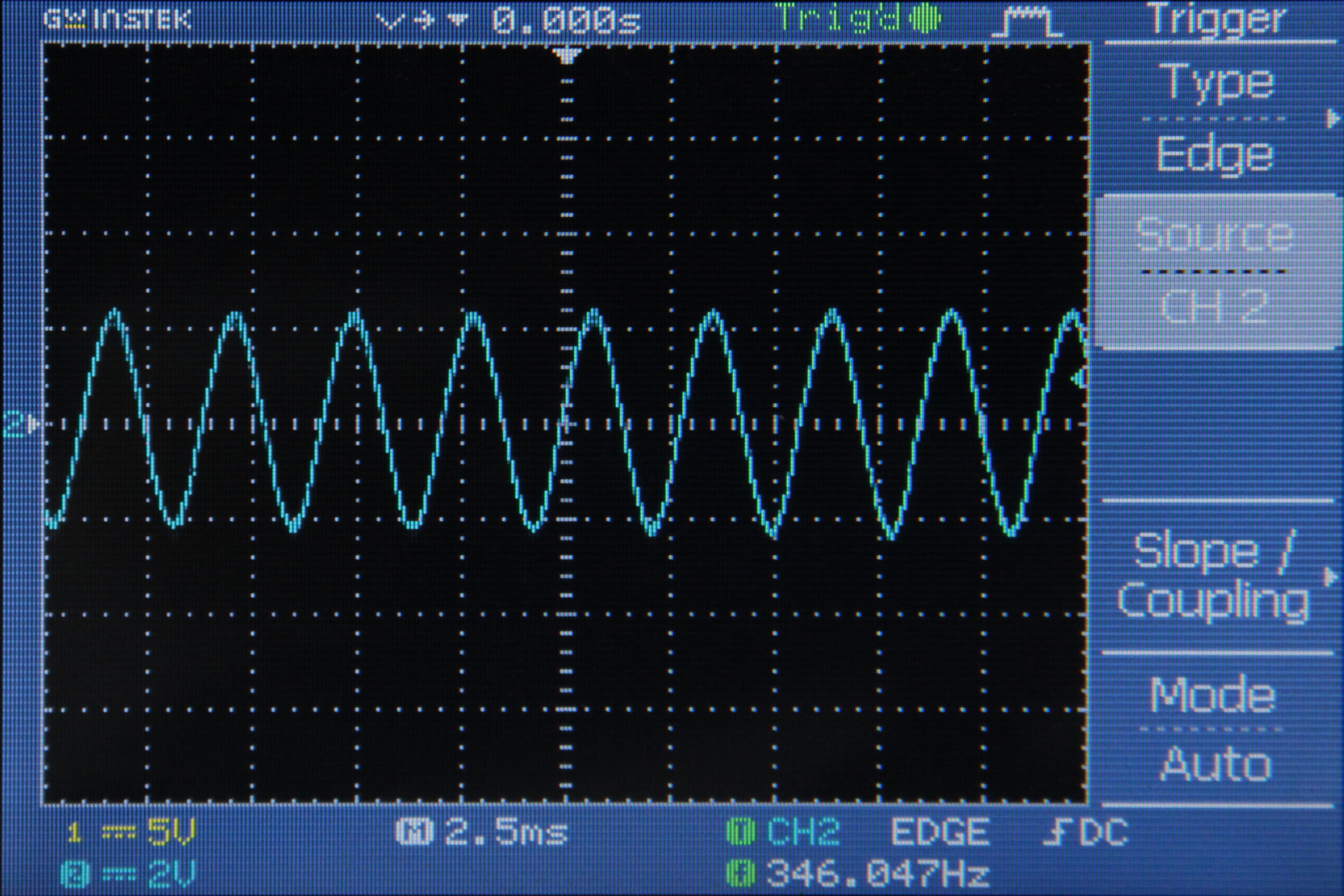 oscilloscope output
The amplitude of the wave is 2V: it reaches a maximum voltage of +2V and a minimum voltage of -2V. This is a problem if we want to measure the audio signal with one of the Arduino’s analog inputs because the Arduino can only measure voltages between 0 and 5V. If we tried to measure the negative voltages in the signal, the Arduino would read only 0V and we would end up clipping the bottom of the signal. My approach to tackle this is as follows:
Min voltage = Center Voltage - Amplitude Min voltage = 2.5V - 2.5V = 0V
Max Voltage = Center Voltage + Amplitude Max Voltage = 2.5V + 2.5V = 5V
 DC offsetting
which can be generalized through DC offsetting. DC offset means changing the center voltage that the wave oscillates around (the average voltage of the wave). It still has an amplitude of 2.5V, but the center voltage is 2.5V instead of 0V, so the wave never drops down below 0V.
These signals are then amplified to get them up to the amplitude we want (2.5V). Amplification means increasing the amplitude (distance between the center point and max or min) of a signal. For e.g, If you wear a hearing aid, you’ll know it uses a microphone to pick up sounds from the world around you and convert them into a fluctuating electric current (a signal) that constantly changes in strength. A transistor-based amplifier takes the signal (the input) and boosts it many times before feeding it into a tiny loudspeaker placed inside your ear canal so you hear a much-magnified version of the original sounds (the output).
The final circuit is as follows:
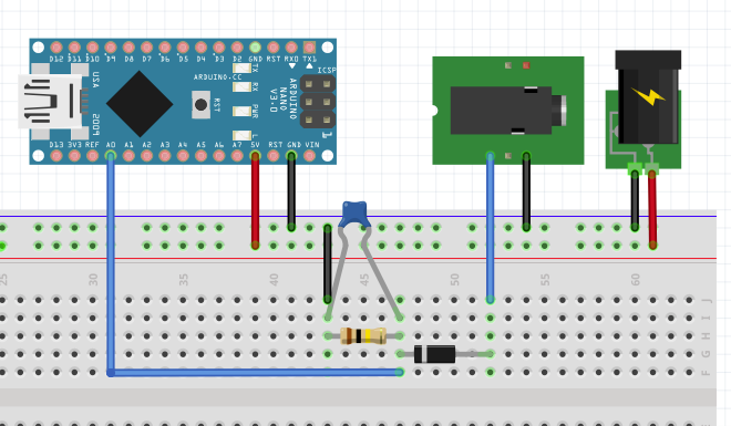 Final AMAJM Circuit
Mechanism Integration(Conclusion):
 The circuit design(discuss above), is then integrated with our Articulate Jaw Mechanism, in which servo controls the close-open movement of the jaw. The ATmega controllers used for the Arduino Uno contain an onboard 6 channel analog-to-digital (A/D) converter. The converter has 10-bit resolution, returning integers from 0 to 1023. While the main function of the analog pins for most Arduino users is to read analog sensors, the analog pins also have all the functionality of general purpose input/output (GPIO) pins (the same as digital pins 0 - 13). The Arduino senses the change in amplitude of Input Audio Signal through its analog pin, thereby Arduino generates the value(between 0~1023) displayed the resultant values in the Arduino Serial Terminal as follows:
Real-time Audio Signal to Serial data Conversion
The AMAJM acts between the audio signal generated from Manav’s speech synthesis algorithm and the Articulate Jaw Mechanism servo. Therefore achieving real-time performance successfully. The AMAJM final design produces the following real-time result:
Amplitude Manipulated Articulate Jaw Mechanism
Hey there, Hope you enjoy reading this article. If so, Share it with your family & friends! So Stay Tuned and Stay Creative ;)